        |
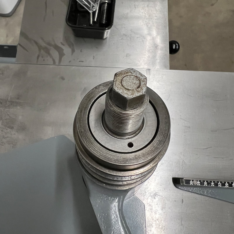
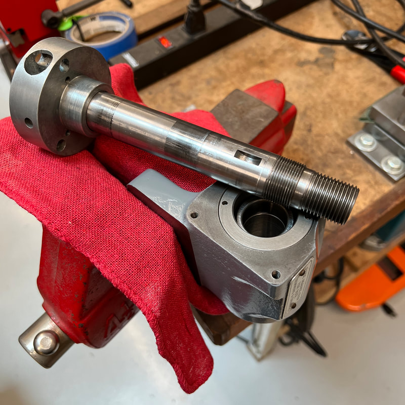
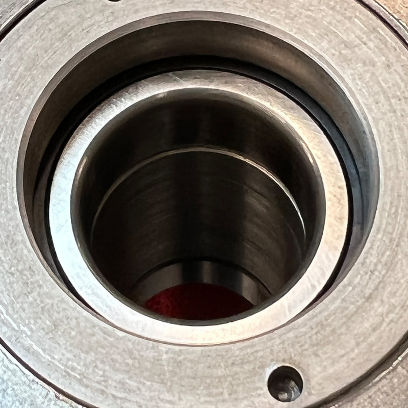
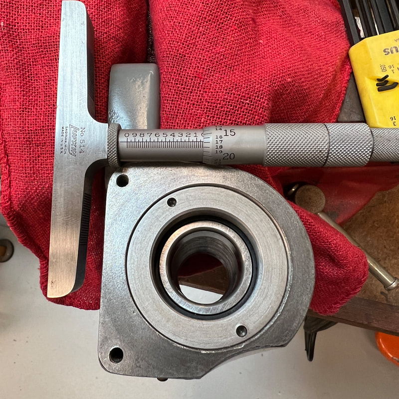
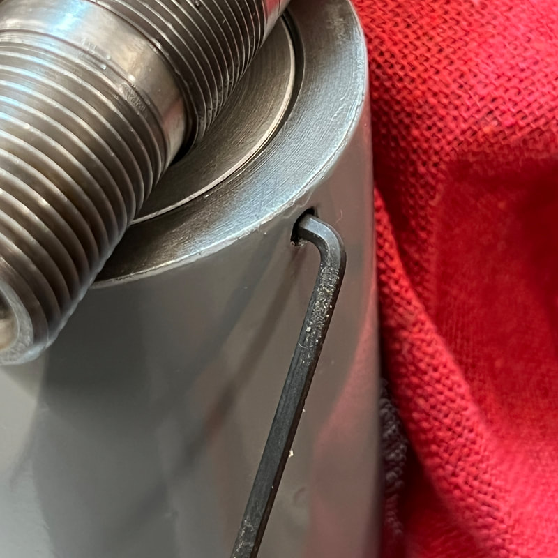
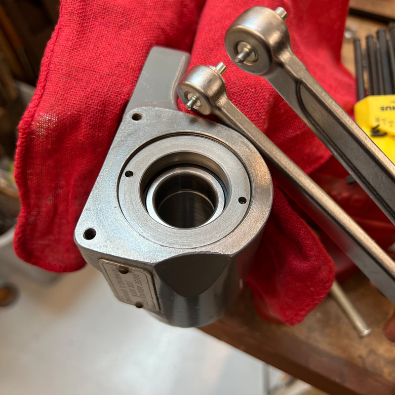
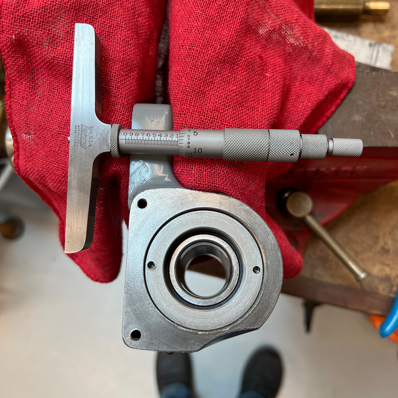
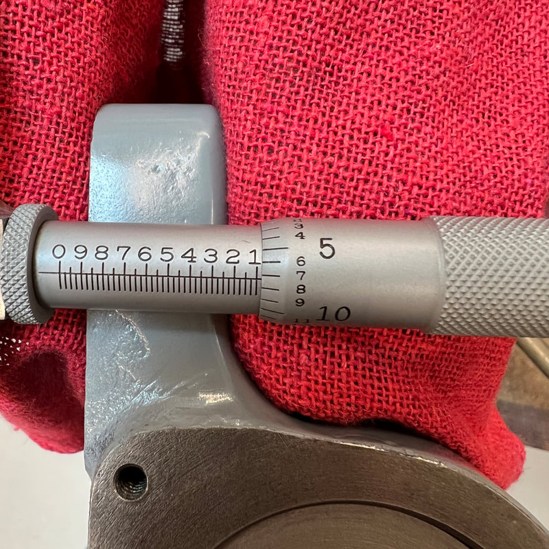
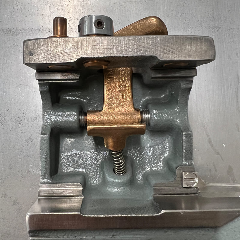
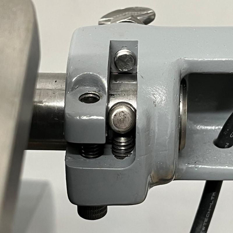
Spindle Re-reassembly to reduce clearance between the blade and the sliding table The bearing retaining rings locate the spindle in the spindle housing. The rings require a face pin spanner to remove and adjust. Thus, the spindle must be driven out of the bearings for access. Clearance between the blade and the sliding table can be adjusted by noting the desired change in position and then moving the bearing retainers the same amount in/out of the spindle housing. The retainers are threaded 20 tpi so a full turn moves a retainer 0.050". But it's better to measure the position directly with a depth micrometer. NB: Loosen the locking set screws on the retaining rings before trying to rotate them with the pin spanner. Don't forget to retighten them when you're done. |
    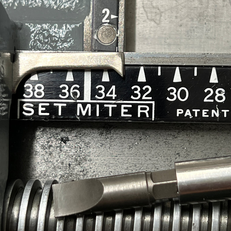 |
Finger adjustment to align pointer with scale
The finger nut position on the finger casting can be adjusted to match the pointer to the correct position on the length scale. Loosen the two locking set screws on the top of the finger casting. Use a screwdriver to move the two adjusting sleeves as required to set the pointer at the desired position. Retighten the locking set screws. |
|
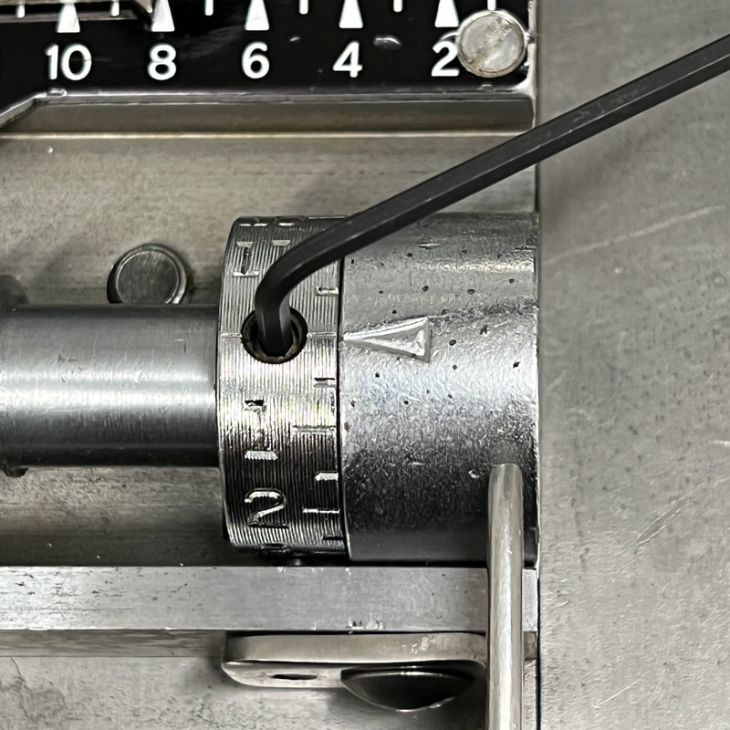
Micrometer dial adjustments
The micrometer dial can be adjusted to read the correct length based on a test cut. Loosen the set screw on the micrometer dial. Rotate the dial by the amount required based on the difference between the indicated length and the actual length of the test cut. Each major numbered division on the dial is 1 point or 0.01383". Retighten the set screw. |
 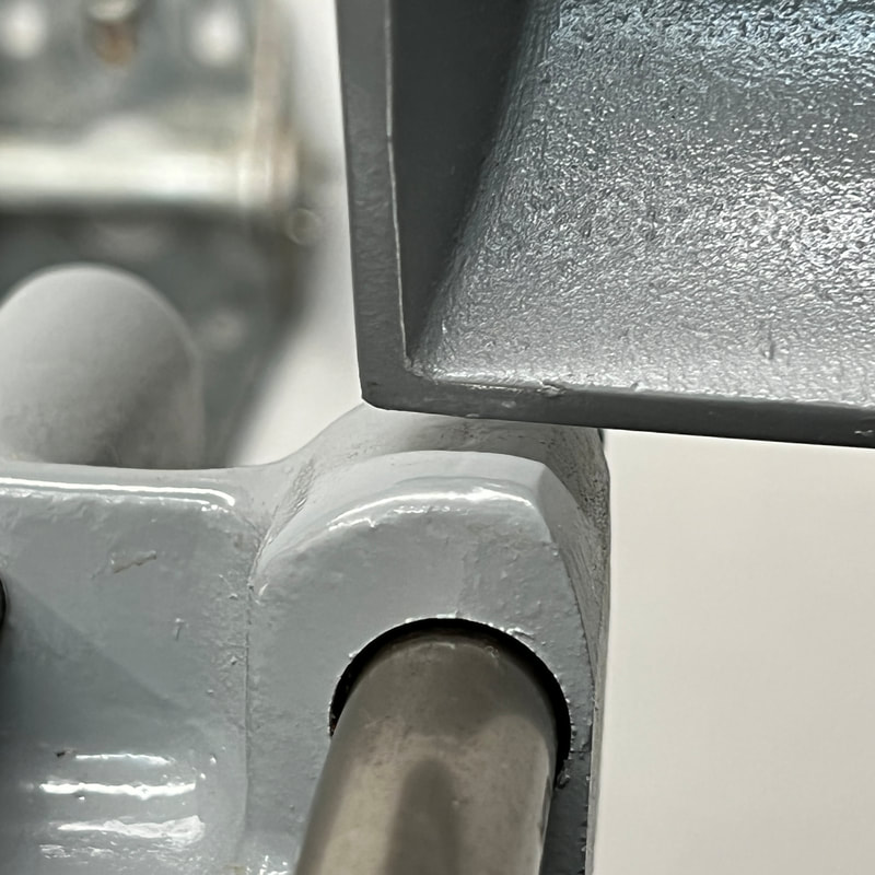  |
Lamp and blade guard assembly adjustments
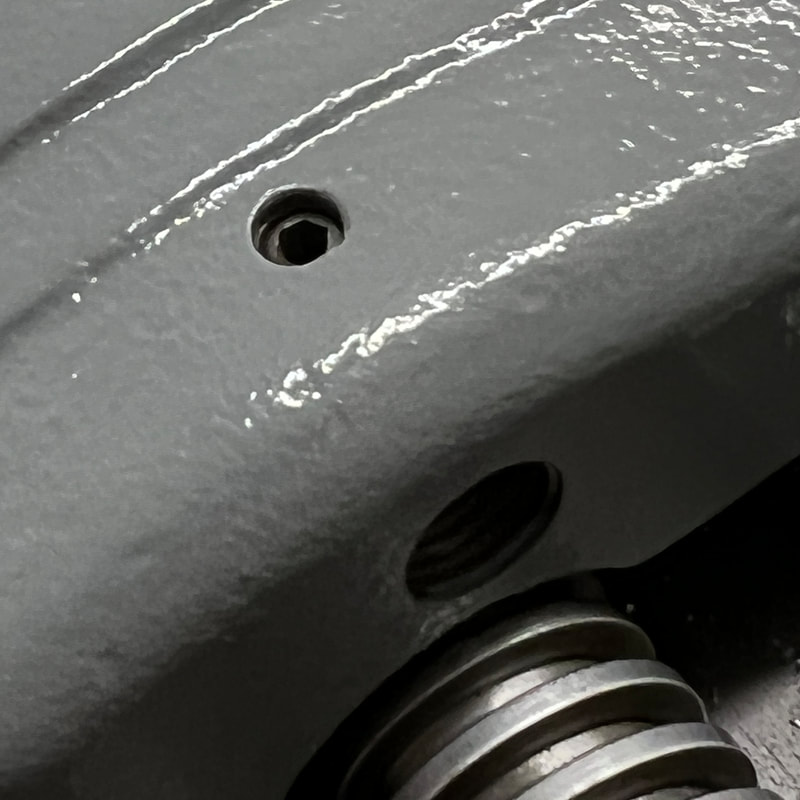
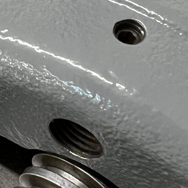
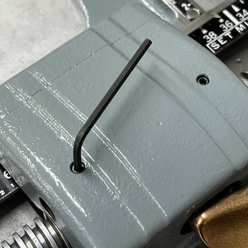
The thumbscrew and set screw set the limits of travel for the lamp and blade guard assembly. (Photo 1) The set screw is adjusted to prevent the blade guard from hitting the clamp assembly when the blade guard is in the fully raised position. (Photo 2) The thumbscrew is adjusted to allow the blade guard to go down as far as possible without hitting the fully raised table. (Photo 3) |
