|
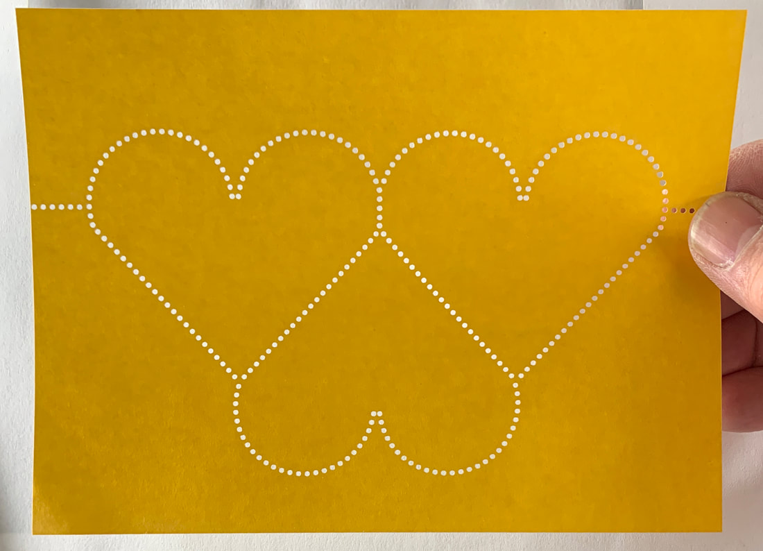
Laser Perforated Sheet
Dry gummed paper 4" x 6 1/8" (254mm x 155.6mm) |
|
My friends at Partners In Print asked me for some specially perforated sheets. Their request gave me a great opportunity to fine tune (and document) how I use a standard CO2 laser cutter/engraver to perforate paper in ways that are impossible with a typical Rosback or Southworth perforator.
The unique advantage of this method is its infinite flexibility. The downsides are that it is sloooooooooow and uses a lot of energy.
The unique advantage of this method is its infinite flexibility. The downsides are that it is sloooooooooow and uses a lot of energy.
|
|
With the laser, you can perforate most any line that you can draw in a vector drawing program like Adobe Illustrator.
Getting good results requires two things: a file with the perforations as vector objects and proper settings for the laser. There is a third step you might want to take if you are are really picky or if you need to make a significant quantity of a single design: a fixture to lift the paper off the bed of the laser in the areas around the perforations. This fixture will make it easier to repeatably locate each sheet on the laser bed and dramatically improve the quality of the cut holes on the back side of the sheet. Let's take these three topics in order. |
|
First, the artwork.
Everything I'm going to describe here will be referenced to my vector drawing tool of choice: Adobe Illustrator. It's likely that there are equivalent work flows in other tools like Inkscape, but I don't know anything about those tools so I can't offer any specifics on how they work. |
|
The workflow in AI is straightforward:
- Draw the paths you want to perforate
- Set the stroke for the path to create the hole shapes
- Make the path into many, many round vector objects
- Fine tune the positions of the holes if required
I'm going to assume that you know how to draw paths. So, let's talk about the stroke settings.
The key concept is that the perforations are formed from a dashed line. The properties of the line (stroke weight, dash length, spacing, and stroke end cap shape) allow us to create lines of round holes that follow the paths perfectly.
The key concept is that the perforations are formed from a dashed line. The properties of the line (stroke weight, dash length, spacing, and stroke end cap shape) allow us to create lines of round holes that follow the paths perfectly.
|
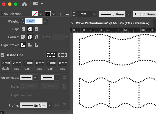
Here are the stroke settings for a typical perforated line.
The "weight" sets the diameter of the perfs. The "gap" in the dashed line sets the spacing of the perfs. The subtle part is to set the stroke to have a round cap and dash to have zero length. That way, all you get is the caps which are semi-circles 1mm in diameter. Stick the two ends together and you get a 1mm circle! The perf diameter and spacing can be adjusted to suit your taste. Here, 2mm spacing would yield 10 perfs in 2cm, so the philatelists would call this "10 Perf" or "Perf 10". For me, Perf 10 is as coarse as I like to go. The typical Rosback or Southworth perforator is more like Perf 14. Finer perfs look great and are easier to separate, but they take far longer to perforate. More about that later. |
|
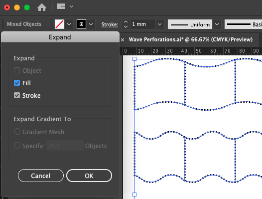
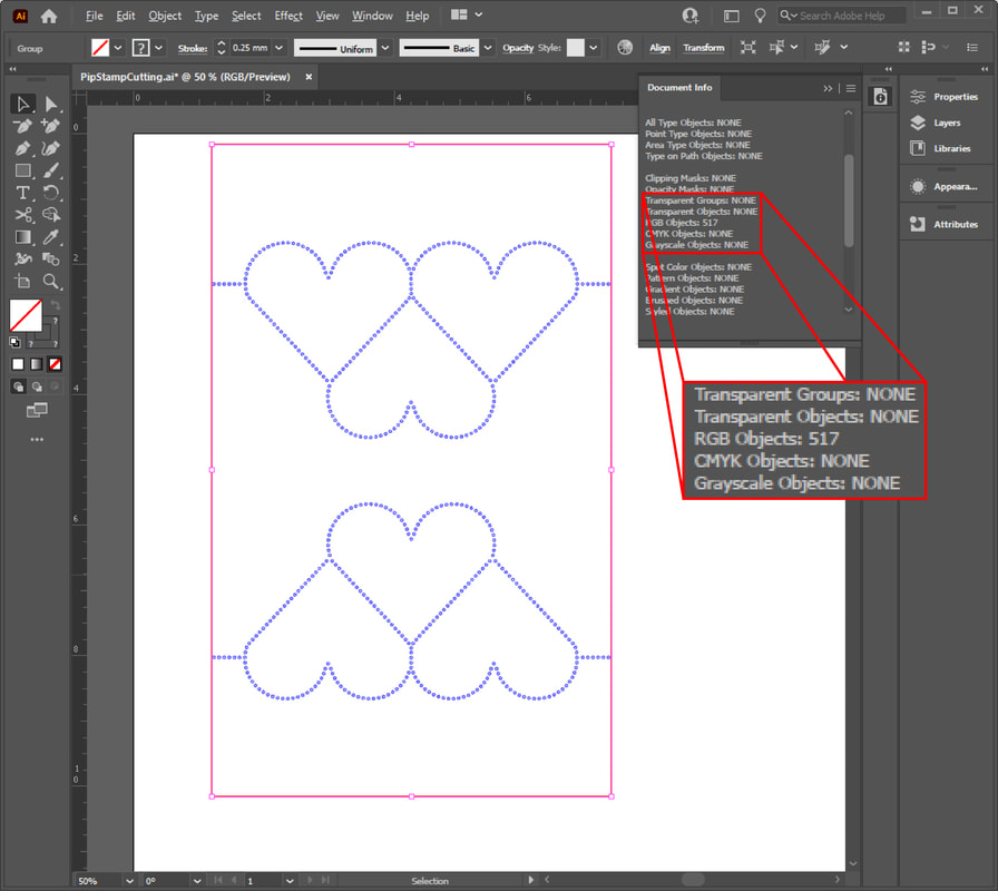
Once you have the lines of perfs where you want them, it's time to convert them into a very large number of actual circles for the laser to cut.
In AI, this is easy: grab all the paths and "Expand" them with the "Stroke" box checked. Now, instead of a small number of paths that look like a bunch of circles, you really have a bunch of circles. |
|
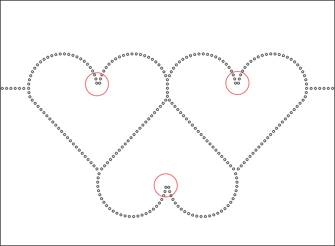
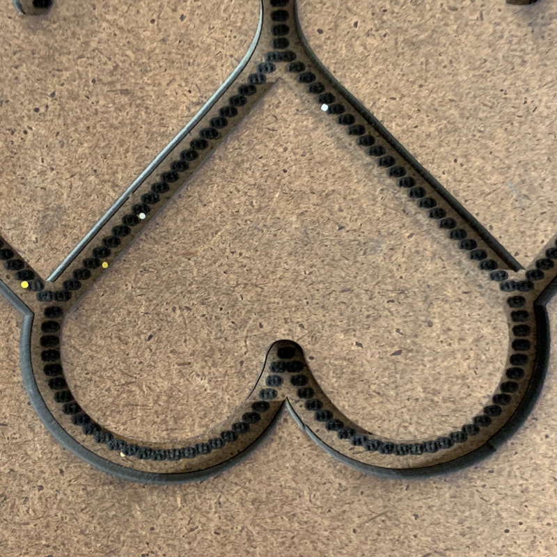
The inner arcs don't come to a point and the last two holes are too close together.
|
Now that you have individual circles to work with, you can fine tune anything you don't like.
For instance, you might want the intersection of two perfed lines to line up perfectly, or two intersecting curved rows of perfs to come together to a nice point. Most people probably won't notice these details but I guarantee you that that some printers would! |
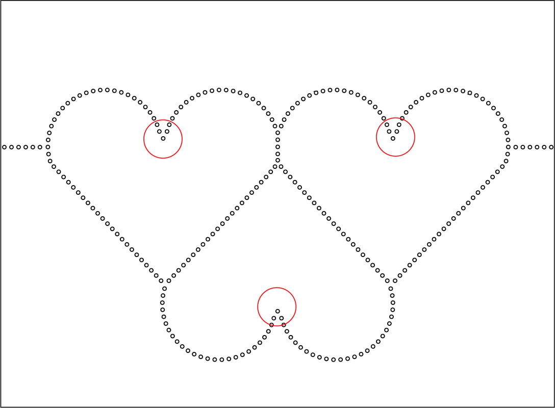
That's better!
|
If you only move the perfs a tiny amount out of position your eye won't detect the distortion of the row of perfs.
If you are really obsessive about this being undetectable, you can grab a bunch of perfs, more them a tiny bit, deselect the one on the end, move the rest a tiny bit, deselect the one on the end, etc., etc. Or so I hear.
That's it for the artwork, you are ready to cut!
If you are really obsessive about this being undetectable, you can grab a bunch of perfs, more them a tiny bit, deselect the one on the end, move the rest a tiny bit, deselect the one on the end, etc., etc. Or so I hear.
That's it for the artwork, you are ready to cut!
|
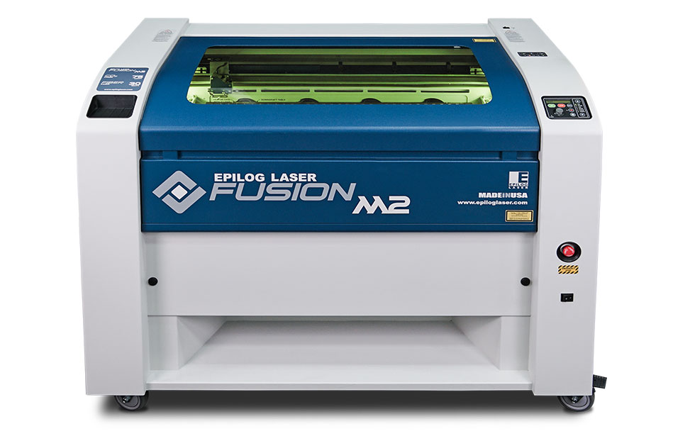
I use a CO2 laser from Epilog Laser for lots of things, including fancy perforating.
The principles I'll describe here are universal and should work regardless of what type of laser you have (or have access to). |
|
To establish the settings for your laser that will yield the best results you'll need to balance two things: time and cut quality.
A typical sheet of fauxstage stamps will have at least hundreds and perhaps thousands of holes, so it's critical to cut as quickly as possible. But, if you just crank up the speed to the maximum and the power to a high value that gives a fully removed perf every time, the odds are good that you won't like the amount of scorching you'll get around each hole, particularly on the back side. |
A little too crispy on the reverse side for my taste.
|
|
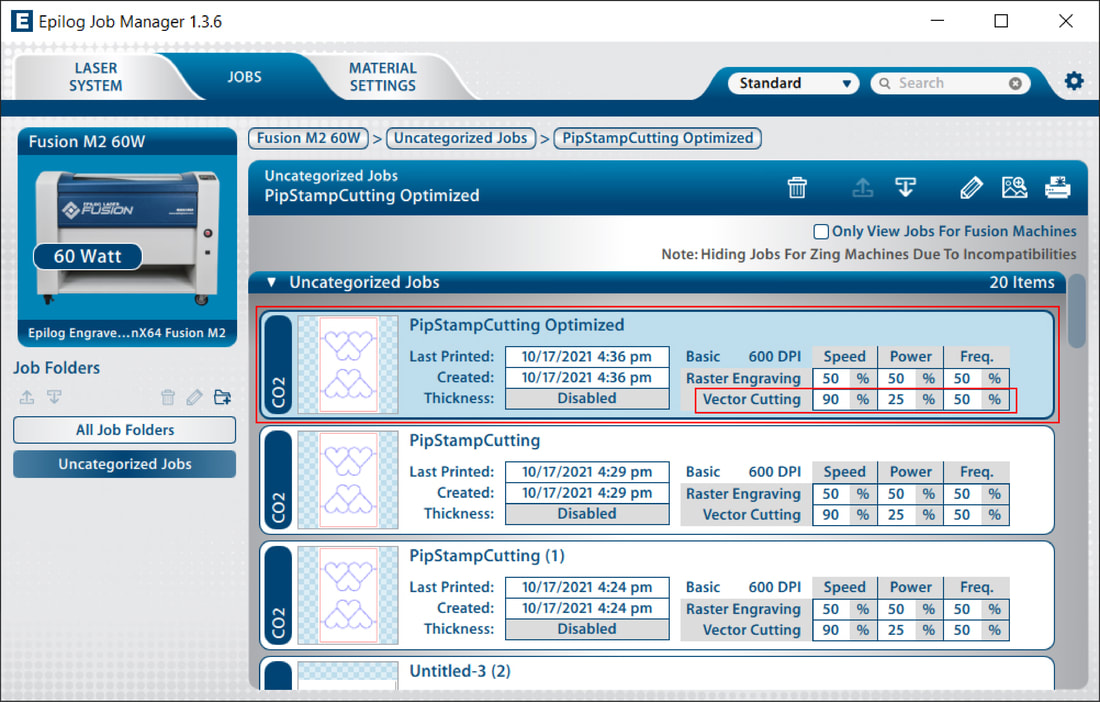
There's really no way around it: for each type of paper you want to perforate, you'll need to try a few different settings to settle on one that is as fast as possible while still giving good results.
Here are the settings for the PiP project as displayed in the dashboard for the Epilog Laser. Epilog Lasers have three knobs you can turn while optimizing vector cutting: speed, power, and frequency. Your laser might have slightly different controls but the goal is the same: run as fast as you can and tweak the other settings to get good quality holes. Here, I had to back off a bit from 100% speed, use relatively low power, and stick with the middle of the frequency range. |
|
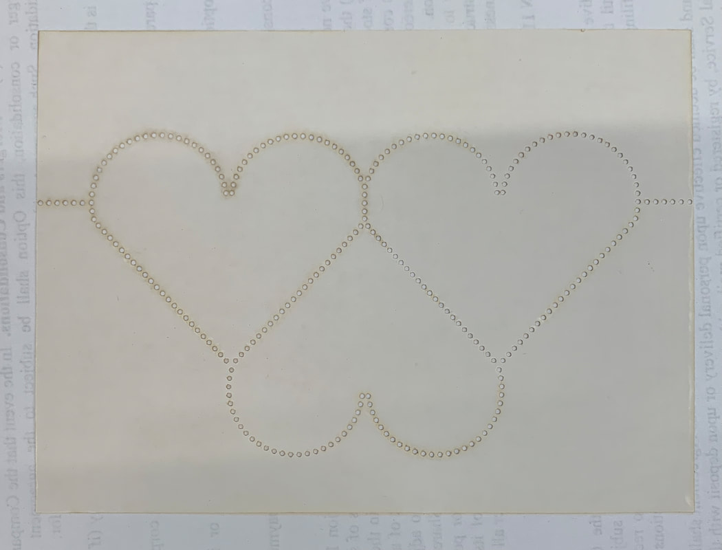
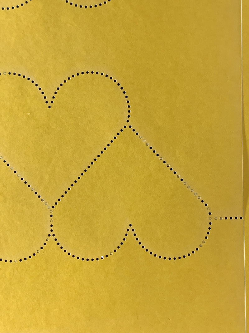
You'll know you've got it dialed in pretty well when almost all of the holes are cleanly "punched" but there are a few that are still hanging on.
The reluctant ones can be ignored (yeah, right), punched out by hand with a bent paper clip or other pointy bit, or (if you are really serious) blown out with compressed air. I'm fortunate to have compressed air in my shop and it made short work of encouraging the last few perfs to clear out. |
|
|
Now that we have the settings, we can figure out how long the job is going to take.
My laser will make about 200 holes per minute with the settings shown above. The sheets for PiP were done 2-up and these had about 500 holes at Perf 10. The total cycle time per 2-up sheet was about five minutes. That time includes loading, perfing, cutting the sheet to size (the pink line here), and blowing off the last few perfs. That might not seem like much, but it adds up fast if you want to make a long run. Making 150 sheets for PiP took about 6 hours of machine time. The cycle time was long enough that I could do other little tasks between loading sheets but that's still a long time. And you NEVER leave the room while the laser is cutting. That's a recipe for burning down your workshop. |
For the entire time the work is underway the laser and the exhaust fan are running. Together they use a fair amount of electricity so this technique should be used when you really need it. Stepping on the Rosback treadle is certainly more eco friendly.
Producing these sheets would have taken even longer if the perfs were finer. All other things being equal, at Perf 14 the machine time to do the project would have gone up to to over 8 1/2 hours. I mean, I like the folks at PiP, but that's a whole lot of time.
Producing these sheets would have taken even longer if the perfs were finer. All other things being equal, at Perf 14 the machine time to do the project would have gone up to to over 8 1/2 hours. I mean, I like the folks at PiP, but that's a whole lot of time.
|
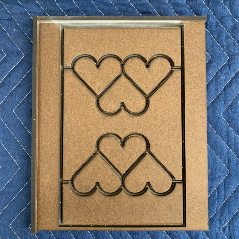
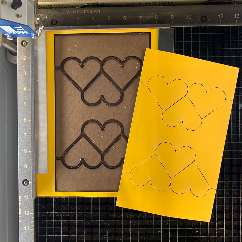
One final topic: another way to decrease (and hopefully eliminate) scorching on the back side is to space the paper up off the laser bed. That way there is nothing directly behind the paper to reflect the laser back up into the paper after it cuts through.
The easiest way to do this is to make a cutting fixture. Cut spacers that are just smaller than the shapes inside the lines of perforations and then glue them down to a backing. We have the artwork for the lines of perforations and a laser, so that's pretty easy to do. Another key feature of the fixture is a fence along the left and top edges. This fence sticks up far enough to allow the paper to just be pushed into the corner and weighted down to register it. Easy. The fixture shown here is made from one of my favorite laserable materials: tempered Masonite (hardboard) with both sides smooth. It cuts and engraves well and is pretty cheap. The downside is that it's not that easy to find. My local lumberyard doesn't stock it but they will order it. NB: this is not the same as what the local big box store will try to sell you as tempered Masonite. That stuff has one roughly textured side and is made from inferior materials. It's terrible to work with in the laser. |
|
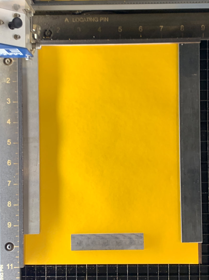
In use, you'll need something to weight down the paper on the fixture so the exhaust fan doesn't move the paper around.
Here I'm using some steel bars and a piece of 6pt slug laid on top of the paper outside of the working area of the design. |
|
|
That's all there is to it!
Just rinse and repeat. |
