I started my professional career as a chemical process engineer. The fingerprints of that perspective are all over what follows below. If you're not a process nerd, you might want to bail out now.
Still with me? Okay then. First a few summary topics.
Still with me? Okay then. First a few summary topics.
Process Summary
Materials
3/8" thick cast acrylic sheet
3/8" thick cast acrylic sheet
Process Steps
Mask printing surface with transfer tape
Engrave all non-printing areas (plate background and white space in designs)
Engrave plate background and any large areas of white space within the designs
Engrave only the plate background twice more to deepen the relief
Engrave two cleanup passes around the outer contours of the designs
Cut out the plate
Remove remaining masking from printing surface
Wash printing surface with detergent and/or solvent to remove adhesive residue and surface contamination
Examine plate with a 10X loupe looking for debris drifted up against the vertical walls of the printing surfaces
Scrape away any significant debris with a sharp Xacto knife or scalpel DO NOT SCRATCH THE PRINTING SURFACE
Proof plate
Examine line quality for any telltale roughness caused by remaining debris
Scrape, proof, and examine in sequence until plate is printing properly
Process Notes
On sequential engraving passes, alternate rastering direction bottom up, top down, bottom up, top down, and so on
Carefully brush away any loose debris on the surface between each pass with an old toothbrush DO NOT MOVE PLATE
On sequential engraving passes, alternate rastering direction bottom up, top down, bottom up, top down, and so on
Carefully brush away any loose debris on the surface between each pass with an old toothbrush DO NOT MOVE PLATE
Laser Specs and Settings
Laser: 60W Epilog M2 with a 2" lens
Raster engraving settings: 90 speed, 60 power, 600dpi
Vector cutting settings: 4* speed, 90 power, 100 frequency (*speed comp turn ON)
Laser: 60W Epilog M2 with a 2" lens
Raster engraving settings: 90 speed, 60 power, 600dpi
Vector cutting settings: 4* speed, 90 power, 100 frequency (*speed comp turn ON)
Artwork
All artwork drawn in RGB black #000000 or converted to same before engraving
All artwork drawn in RGB black #000000 or converted to same before engraving
Expected Results
The conditions above yield a shallow (approximately 0.008" or 0.2mm) relief for the design details and a deeper (approximately 0.027" or 0.7mm) relief for the large, non-printing areas of the plate.
NB: The shallow relief was enough to get clean prints for this project because I used hard packing on the press and smooth, hard stock for the stamps. For softer papers, more relief would almost certainly be required.
Design Constraints
The minimum white space between design elements is about 0.012" or 0.3mm.
Again, this is the minimum white space between adjacent printed areas, not the minimum line width that would print. It's possible to hold line widths down to 0.004" or 0.1mm.
The for this project, this constraint dictated that the stamps needed to be about 1.2" x 1.2" or 30mm x 30mm. At this size, the finest details in the designs were within this constraint. Full disclosure: I actually came at this the other way. I set the approximate stamp size and then tried to draw something I liked within this constraint.
That's it. A lot of learning, gleaned over most of a year, condensed as far as I can.
There's a ton of detail behind this condensed version. For the true process nerds, I'll carry on with the details below, taking them in the order they appear above.
There's a ton of detail behind this condensed version. For the true process nerds, I'll carry on with the details below, taking them in the order they appear above.
Materials: 3/8" cast acrylic sheet
|
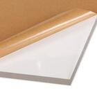
The nuance here is cast vs. extruded acrylic sheet. Each material has its advantages and disadvantages.
Cast acrylic is more expensive and has greater thickness variation. It also engraves better, is resistant to solvents, and has few stresses in the sheet after manufacturing that might cause a deeply engraved plate to warp. Extruded acrylic is cheaper and more consistent in thickness. It engraves ok, but is more likely to warp due the stresses trapped in the material during manufacturing. The real down side to extruded acrylic is that it is much less solvent resistant than cast acrylic. I routinely clean the surface of laser engraved cast acrylic plates with isopropyl alcohol (IPA) if they have contamination on the surface. (I start with a good scrubbing with water and detergent but sometimes that's not enough.) I've never had an issue with IPA and cast acrylic. By contrast, laser cut extruded acrylic can craze, crack, and even fall to pieces under some conditions when exposed to alcohols and some other solvents. |
Don't take my word for it. Here's a 20 min. video on the evils of solvents and their affects on acrylic.
Note that the author makes no distinction between cast and extruded acrylic in this video. But if he bought his test material at a big box hardware store, it is almost certainly extruded. |
Mask printing surface with transfer tape
|
Laser engraving and cutting produces debris and surface contamination that are much harder to remove than to prevent.
The transfer tape used to apply die cut vinyl stickers works great as a mask. It's thin, sticks to the surface well, and comes off (relatively) easily after engraving. Transfer tape is a better mask than the brown protective paper that comes on the acrylic sheets because the protective paper is much harder to remove after engraving. Be sure to get all the air bubbles out of the mask layer before engraving. Bubbles can cause variations in engraved depth. If bubbles can't be worked to the edge and removed, use a pin to poke a tiny hole in the mask and burnish the mask down to the surface. |
Good masking
Bad masking
Images from Amazon.com
|
|
This is ultimately what it's all about. I tried numerous experiments with laser settings varying power, speed and resolution. I tried different lens focal lengths.
In the end, the basic acrylic engraving recipe provided by Epilog Laser did the best job at engraving the designs. 90 speed, 60 power, 600dpi, 2" lens. The most surprising observation was that increasing the engraving resolution from 600dpi to 1200dpi actually reduces the line quality. I don't have a well supported theory as to why this is the case but I'm not beyond speculating. Maybe doubling the dot density caused more melting in areas adjacent to what is being engraved even at lower power and the lower power meant shallower engraving. Maybe. Another surprising observation was that reducing the focal length of the lens from 2" to 1.5" also reduces the line quality. This is a real stumper because the spot size of the laser should be smaller and consequently capable of engraving finer details. But it doesn't. Not at any power/speed combination. No idea why. A final nuance to the engraving settings: I tried engraving with the purge air (called "air assist" by Epilog) both on and off. With the air on, the engraving was deeper, all other settings being equal. A side effect is that a lot more debris and contamination were created by each pass. Given how much grief this caused, I switched to engraving only with the purge air off.
Engraving time for one pass was about 8 minutes. Plate size 3 5/8" x 4 1/8" or 93mm x 105mm.
|

Excerpted from epilog.com
I made lots of tests like these to look at different combinations of feature size and laser settings.

The white stuff all over this plate (masked with blue tape) is debris from engraving with the air assist on.

Artwork for the first pass on the black plate (plate 16b).
|


Engrave plate background and any large areas of white space within the designs
|
The shallow relief created by the first engraving pass is enough to get good quality impressions of the detailed designs. But this relief wasn't enough to prevent the larger white space areas from inking and printing.
To keep these interior areas from printing, I engraved them (and the backgrounds areas) a second time. There were few enough of these large interior areas that the small amount of line quality degradation caused by the second pass was tolerable. To engrave only the background and large interior areas, new artwork (without the detailed areas of the design) was required.
|

This is plate 16a, the blue plate used for the stamp run. Note the shallow relief in the detailed part of the designs.

Artwork for the second pass on the black plate.
|
Engrave only the plate background twice more to deepen the relief
|
To prevent the background from inking and printing, two more engraving passes (bringing the total on the background to four)
were enough to give me about 0.027" (about 0.7mm) of relief equivalent to a shallow photopolymer plate. Yet another version of the artwork was required to engrave only the background. Same as above, with the interior areas turned off.
|
Plate 16b showing the depth of background releif.

Artwork for the 3rd and 4th passes on the black plate.
|

Engrave two cleanup passes around the outer contours of the designs
|
The masking prevented debris from sticking to the printing surface. But, as the exhaust fan pulled the debris away from the work area of the laser, the debris would flow across the surface of the plate and accumulate like snow drifts at the vertical walls of the printing areas. These drifts were slightly melted together and stuck to the plate. They could not be removed with a good toothbrush scrubbing.
The drifts were high enough to print if not removed. The telltale signs of debris present on the plate was a ragged line. The image at right shows a lot of ragged areas where the plate needed attention. The drifts could be removed by scraping them away with a sharp blade, but this was tedious and it was easy to accidentally scratch the printing surface of the plate. Minimizing the scraping was required. |

Glassine interleaving plate proof with notes
|
|
The other way to get rid of the debris was to engrave it away. The trick was to find a way to do this without generating more debris. This was possible if only a very narrow "halo" around the designs was engraved. Compare the two images at right.
Side note: The keen eyed observer will note that the lines delineating the ship's decks are missing from the primary engraving art. That's because I used the vector cutting mode at low power to cut the lines instead of cutting them in raster engraving mode. It worked great for these closely spaced, straight line features. |

Artwork for primary engraving
|
|
The halo engraved around the design is 0.010" or 0.25mm wide. Engraved twice to insure that most of the debris were removed.
|

Artwork for halo engraving
|
Cut out the plate
|
Simple vector cut through the sheet of 3/8" acrylic to free the plate.
It was critical that exactly the same art was used to cut out all of the plates that were registered to each other. Any variation in the cut outline or the position of the art relative to the cut outline would translate directly into misregistration. Using the same art was straightforward since the art for all plate colors was in the same Illustrator file. There was only one cut outline in the file and that was used for all plates. Vector cutting settings: 4* speed, 90 power, 100 frequency (*speed comp turn ON) |

Same art, same settings, same location on the laser bed
= Same size plates to register against the furniture |
Remove remaining masking from printing surface
|
The Oracal transfer paper used to mask the plate was fairly easy to remove by running the plate under warm water and scrubbing with a medium soft bristle plastic brush designed for cleaning potatoes. (No idea how this ended up in the workshop, but it worked great.) Any masking that wasn't removed by the brush was easy to gently scrape off with a fingernail.
|

Does random stuff just accumulate in your workshop too?
|
Wash printing surface with detergent and/or solvent to remove adhesive residue and surface contamination
|
After the paper mask was removed or at least mostly removed, I continued scrubbing the plate using a ultra dishwashing detergent and the bristle brush.
If there was any residue left after that, I used a cotton rag and 99% isopropyl alcohol (IPA) to remove it. Do not confuse this kind of IPA with the kind from the local brew pub. Your insides will thank you for making the distinction. |

|
Examine plate with a 10X loupe looking for debris drifted up against the vertical walls of the printing surfaces
|
The halo engraving passes removed most of the debris most of the time, but there was always a stubborn little spot or two that needed to be removed by hand. These were usually easy to see on the plate under 10x magnification.
(This plate is a mess - residue pretty much on every contour. That's why it never even got proofed.) |
  |
Scrape away any significant debris with a sharp Xacto knife or scalpel DO NOT SCRATCH THE PRINTING SURFACE
|
The remaining debris were scraped away from the edge of the printing areas of the plate using a sharp Xacto knife. A scalpel would work too as long as it was on of kind with a pointy blade.
Stand the knife on its tip with the sharp edge against the edge of the printing area, and gently drag the sharp edge of the knife along the edge of the printing area. Multiple light, well controlled passes were safer than trying to remove the debris all at one go. The big risk here is that the knife slips and gouges the plate printing surface. Despite my caution, this happened to me more than once. There's nothing you can do to repair a scratch like this. The only choices are live with it or remake the plate. |

Working with a blade this close to the printing surface is not for the faint of heart or those with unsteady hands.
|
Proof plate
|
Proofing the plate was the only certain way to know if all the debris were gone and that the overall engraving was good.
|
You know what a proof is, right? Good.
No picture required here, then. |
Examine line quality for any telltale roughness caused by remaining debris
|
Examine the proof for rough lines and compare to the plate to see if you missed anything that needs scraping on the first examination.
The same 10x loupe works fine for this if you want something higher rez than the naked eye. |

Some of the areas needing attention on this proof are marked in green
|
Scrape, proof, and examine in sequence until plate is printing properly
|
Lather, rinse, repeat as above until the proof looks good.
|

That's better
|
On sequential engraving passes, alternate rastering direction bottom up, top down, bottom up, top down, and so on
|
The way the debris accumulate on the edges of the printing areas depends on which direction the engraving is done.
To minimize the accumulation on any one side of the raised printing areas, alternate the direction of the rastering. The Epilog laser has a simple setting in the print dialog to specify the direction. |

|
Carefully brush away any loose debris on the surface between each pass with an old toothbrush DO NOT MOVE PLATE
|
Even with the air assist turned off, debris did end up on the printing surface and background of the plate on each pass. Removing these gave the best chance that all areas of the plate would engrave easily. Brushing the surface removed most of the debris.
Note that brushing with the toothbrush did not remove fused debris drifted up against the vertical wall of the printing surface. The risk here is that while brushing the surface the plate moves out of position. If this happens there's no solution other than starting over on the plate. There's no way to get it back exactly into position after it has been moved. The good news is that it's easy to hold the plate down to the engraver bed with one hand while brushing with the other. I never had to remake a plate because one moved while I was cleaning it. |

Toothbrushes only move FROM the house TO the workshop. Otherwise...yuck.
|
Laser Specs and Settings
|
Laser: 60W Epilog M2 with a 2" lens
Our Epilog Laser Fusion M2 is a fairly standard 60W CO2 laser. Although 1.5" and 4" lenses are available, the 2" lens worked the best for this project. See above. Raster engraving settings: 90 speed, 60 power, 600dpi
The standard Epilog recipe for engraving text or clipart on acrylic worked well. This speed was near enough to the maximum that it wasn't worth trying to optimize the power at 100 speed. Again, see above. Vector cutting settings: 4* speed, 90 power, 100 frequency (*speed comp turn ON)
Cutting 3/8" acrylic on a 60W laser is near the thickest possible cut and thus requires nearly the slowest speed. The Epilog laser driver has a setting called Speed Comp. This setting allows more precise speed settings at very low speeds by dividing the speed setting by 2. So if 5 speed is too fast and 4 speed is too slow, set the speed at 9*, which is equivalent to 4.5 speed. I could have just set the speed at 2 instead of 4*, but the test that set this value was done at 4* and it wasn't worth redoing it just to simplify the setting. I never run the laser tube up to 100 power, figuring that the tube life will then be that much longer. This practice is a holdover from my days working with Epilog lasers at TechShop (may it RIP). The more like acrylic and the less like wood a material is, the higher the frequency required to get a good cut. Lower frequencies on polymeric materials don't have the concentrated energy to vaporize them well and higher frequencies on wood cause excessive charring. So 100 frequency it is. |

Image from Epilog Laser.

|
Artwork: All artwork drawn in RGB black #000000 or converted to same before engraving
|
The Epilog laser print driver works from RGB settings to adjust the laser settings automatically for things like engraving continuous tone images in photographs. Pretty cool, but all the engraving here is done as a solid at the same depth per pass, pure black (RGB value #000000) is the desired setting for areas to be removed and pure white (RGB value #ffffff) for the printing areas.
If you want to get fancy, the Epilog laser can work off artwork containing different colors to set different laser conditions. This is useful if you want to engrave with different conditions in the same run. Slick, but not useful for this project. |

Artwork for the first pass on the black plate (plate 16b).
|
Expected Results
|
The relief required to get a good impression depends on a number of variables. Generally, the deeper the relief, the less you have to worry about any of them. That's why typical drive depths for both metal type and photopolymer plates are between 0.027"-0.055" (0.7mm-1.4mm).
To get the highest quality engraving on acrylic, the laser power has to be set just right. Too low and not much happens. Too high and the adjacent areas of the plate melt. A lot of what was summarized above was about how to use the best settings to achieve the required depth. The laser conditions used in this project were optimized so that a single pass gave enough relief (approximately 0.008" or 0.2mm) to give a good impression with reasonable line quality. But this is only proven to be true for the paper and press conditions I ran. The press packing was on the hard side: 4 sheets of tympan, a 0.007" (0.2mm) polyester (Mylar equivalent) top sheet, and two pieces of 20# copy paper. Our press has a 0.040" cylinder undercut. The gummed stamp paper was 55# and had a smooth surface (a so-called English Finish). It's on the hard/smooth side for most of what I've seen used for letterpress printing. The paper proofs were run on generic 20# copy paper. About the same thickness as the gummed stamp paper but with more texture. The plates printed fine on both papers.
The resulting impression was deep enough be seen on the back side of the gummed sheets so it was far from a kiss impression. Even at this depth of impression, the designs printed cleanly because the shallow relief areas of the plate were not inked below the surface. I guess eventually I had the form rollers set right. Even so, as summarized above, the background of the plate had to be engraved far more deeply to prevent it inking and printing. The four passes it took generated a lot of debris and managing those debris added a lot of complexity to the process. |

Detail of plate 16b showing the combination of shallow relief in the detailed areas of the design and deep relief in the larger open areas and the plate background.

Pretty deep impression on such thin paper (20# copy paper).
|
Design Constraints
|
The resolution of this method overall is dictated by the minimum feature size that can be cleanly engraved. It turned out that feature size as we normally think of it I.e. minimum line width is not the primary constraint here.
Because the laser is removing the white space from the surface of the plate and leaving the printing surface intact, the primary constraint is the space between adjacent printing surfaces. It took awhile to get my head wrapped around how to design using the white space instead of the printed image but after awhile (say when I was 95% done with the project) it was getting easier to think that way as I went. |

|
Had enough? Okay, choose your own adventure: back to the general laser engraving bit, or on to finding paper for the project.
