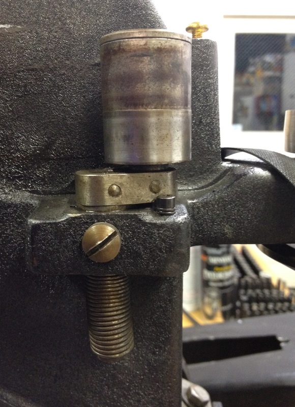
Belt tension assembly mounted on right side of press.
This isn't working quite right. When the press is in low range, the A-998 Coil Spring at the bottom of the assembly is not strong enough to hold the A-108 Belt Tension Idler away from the A-2 Head casting and prevent it from rubbing.
Also, the idler doesn't spin freely on the A-122 Idler Shaft. The idler assembly tends to warm up while the press is running, indicating that there is excess friction in the assembly.
Exactly how to get the assembly apart isn't clear. The belt tension idler is just a tube with bearings and a shaft in it. The top piece (A-124 Idler Cover) presumably comes off somehow. Prying on the split between the idler and the cover seems like a bad idea.
Perhaps after the idler is removed from the A-121 Idler Link, I can drive the shaft out and the cover off from the bottom. Not sure though as the parts diagram calls out a A-123 Retaining Screw at the top of the assembly. It's not clear exactly where this screw is and what it retains.
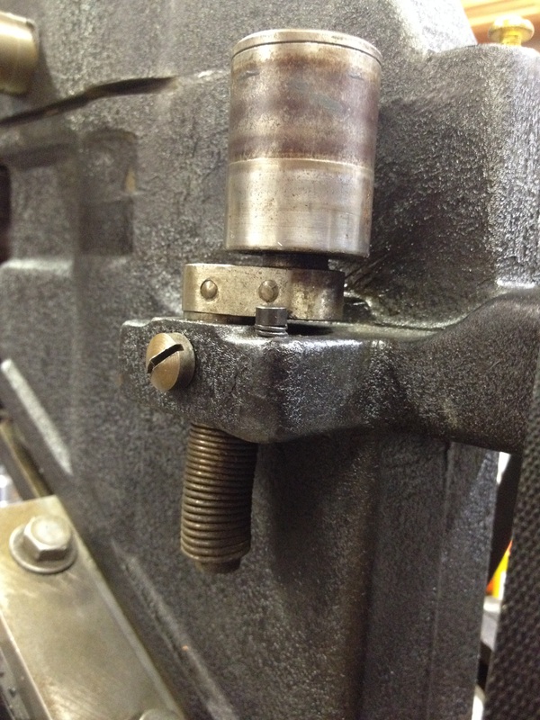
Rear view of belt tension assembly.
|
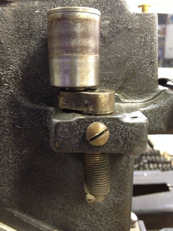
Front view of belt tension assembly.
|
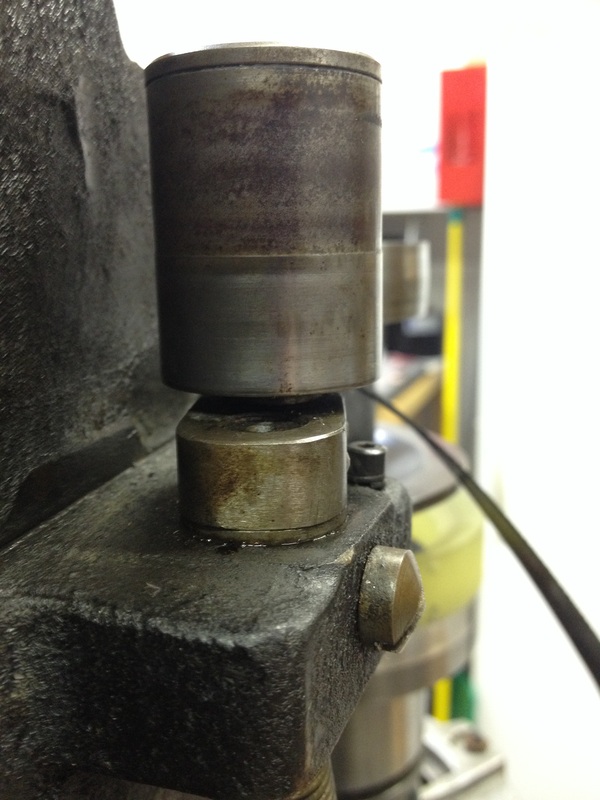
Side view of the belt tension assembly after removing the 6-32 SHCS from the flange of the A-2 Head casting.
I'm not sure that the SHCS is original to the press. I've seen other pictures of these presses and the screw is not present. Perhaps it was a later shop addition design to prevent the idler assembly from rotating forward past its normal operating range when the belt was removed.
This shot also shows a clear view of the A-119 Idler Shaft Locking Screw, a 4-40 machine screw that holds the A-998 Counter Poise Spring onto the A-109 Idler Swivel Stud.
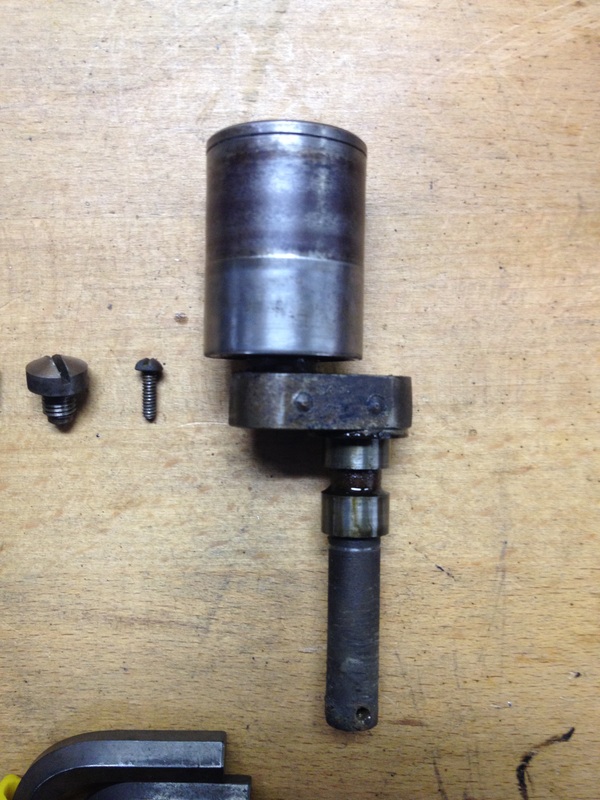
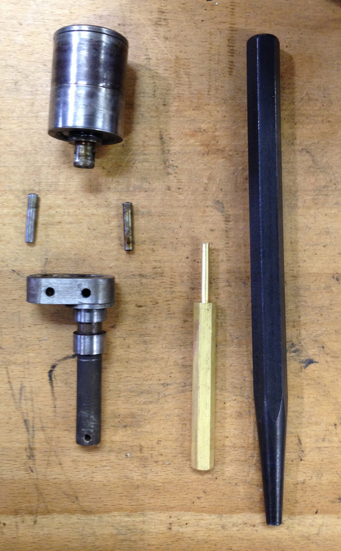
Belt tension assembly (minus the A-998 Counter Poise Spring) dismounted from press.
Removing the assembly required removal of the 1/4-28 fillister head screw from the side of the A-2 Head casting and the A-119 Idler Shaft Locking Screw, a 4-40 round head machine screw that holds the A-998 Counterpoise Spring to the A-109 Idler Swivel Stud.
Note the flat point of the fillister screw that retains the idler swivel stud in the head casting by riding in the groove in the shaft.
I had to hold the counter poise spring in position as I removed the 4-40 screw to keep the spring from unwinding and flinging the screw across the room. The spring has a small hook on the end which is fixed under the head of the screw.
Note the two taper pins which retain the idler swivel stud and the A-122 Idler Shaft on the A-121 Idler Link. This side shows the smaller diameter ends of the taper pins.
The arm and the pins have some hammer/punch scars on them indicating removal (or at least attempted removal) at some point in the past 64 years. I need to find/make a brass drift to knock the pins out so I don't perpetuate the cycle of abuse.
The lower part of the idler swivel stud that was under the spring looks pretty nasty, but I think it's just decades of dried grease/oil. Should clean right up.
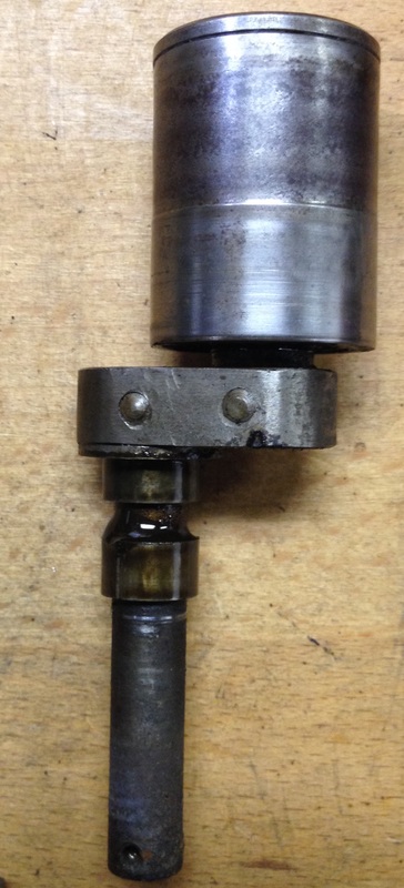
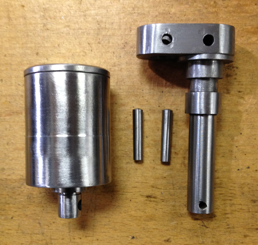
Belt tension assembly (minus the A-998 Counterpoise Spring) dismounted from press.
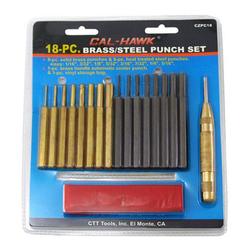
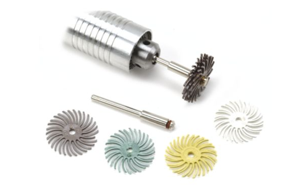
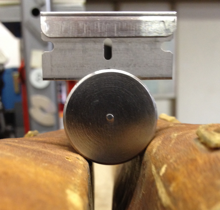
This side shows the larger diameter ends of the taper pins that hold the A-109 Idler Swivel Stud and the A-122 Idler Shaft onto the A-121 Idler Link. More hammer/punch scars on this side, too. One of the pins has a pretty big flat hammered on it. I guess some Evil Doer was unclear on which end to hammer. Bastard. After looking at making a brass drift to remove the taper pins, I decided to just buy a set off eBay from Hobby Tool Supply. The set at right was $15.00 delivered. Not sure I could even buy the brass hex stock for that. I'm not expecting much from the steel punches, but maybe they'll be good for a single use! Ditto for the automatic center punch. |
|
|
Removing the taper pin from the A-109 Idler Swivel Stud was a matter of a couple of taps with the drift.
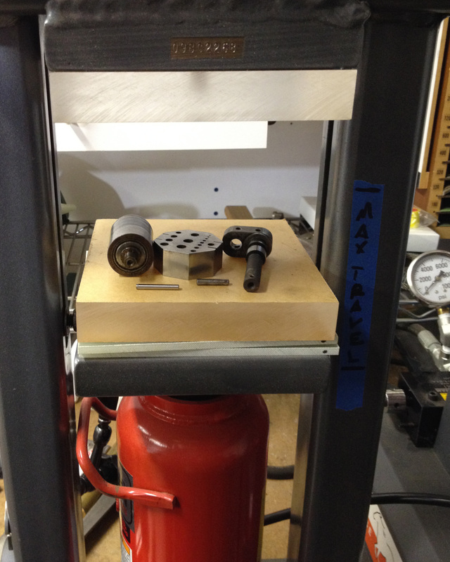
Not so for the pin in the A-122 Idler Shaft. After hammering away at it with the brass drift, I switched to the steel one to no avail. Now I understand all the whaling away that had been done to pin in the past. I had to resort to pressing it out using my Bonny Doon Engineering hydraulic press (a small 20 ton press designed for jewelers). I put the slightly protruding larger diameter head into a hole on my little watchmakers staking anvil and used a 1/8" dowel pin to press it out. It was a bit of a trick to get the dowel pin plumb with the world and centered on the end of the taper pin, but I managed to do so without having to chase the dowel pin all over the shop. |
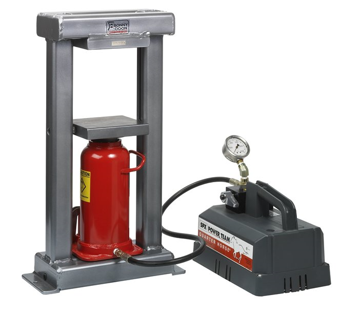
image from riogrande.com
|
|
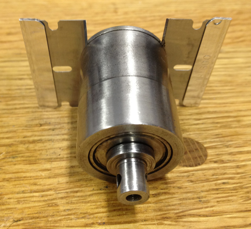
I used a big steel drift to drive the A-122 Idler Shaft out of the A-121 Idler link.
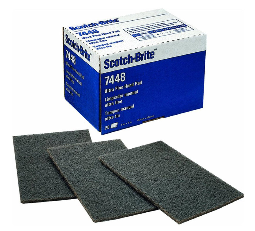
I cleaned up the parts while the A-980 Ball Bearings were still all safely sealed up in the A-108 Belt Tension Idler. Some gray Scotchbrite and 36 grit (brown) 3M Radial bristle discs did the trick. The 36 grit discs are much less aggressive than a typical 36 grit shop roll.
|
|
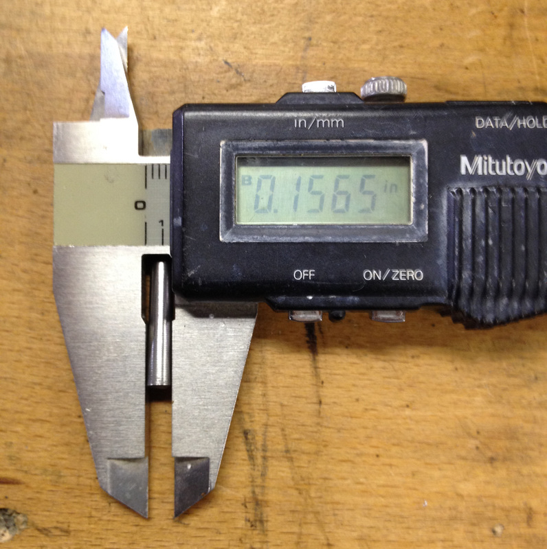
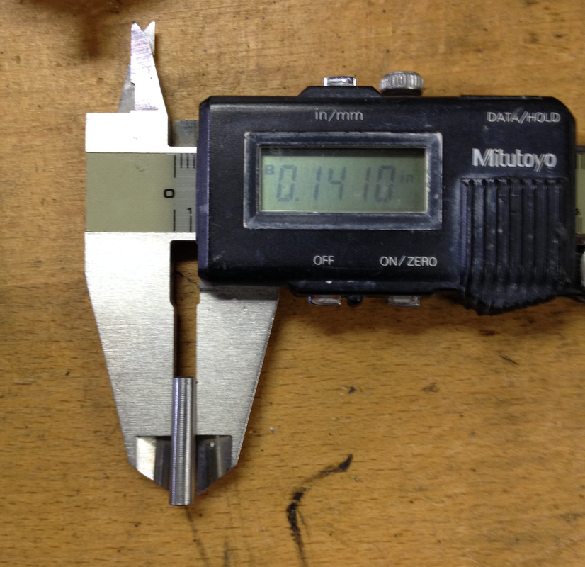
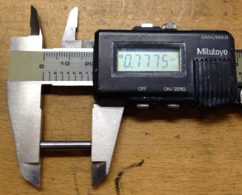
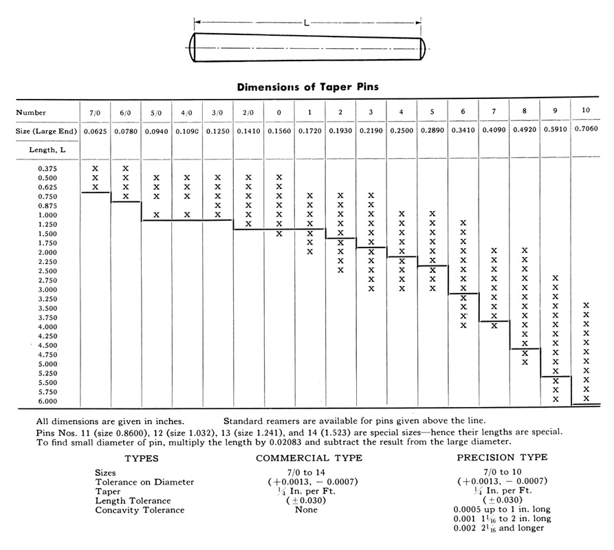
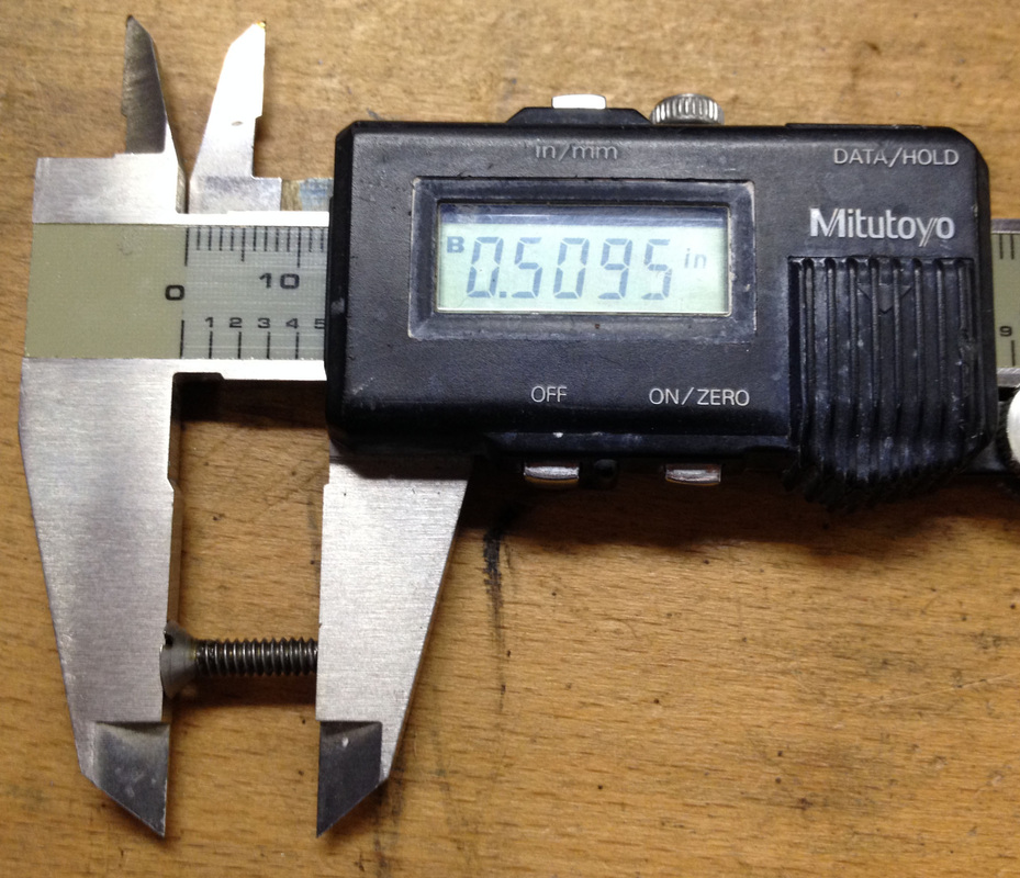
With the pins out, it's a good time to get some measurements of them. The small end diameter is 0.141" (3.6mm) and the large end diameter is 0.1565" (4.0mm). Overall length (after a few decades of having the ends bashed) is 0.778" (19.8mm). These look like size 0 American standard taper pins. Hard to believe they've been mashed flat enough to lose 0.100" of length, and there is a .030" length tolerance according to the chart, so call these 3/4" pins.
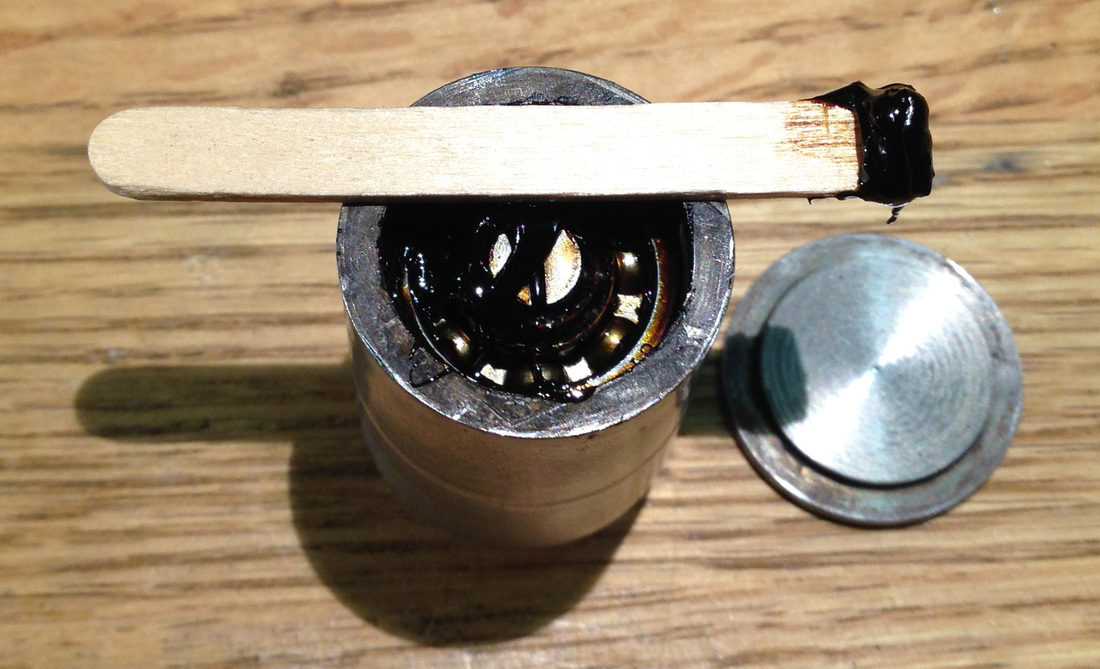
The next challenge was to figure out how to get the A-124 Idler Cover off. Just going at it with a screwdriver seemed like a guaranteed way to put a lot of bozo marks all over the cover and the A-108 Belt Tension Idler.
I decided that tapping a stout knife blade into the gap might work...but my bench knife has gone walkabout. Now what?
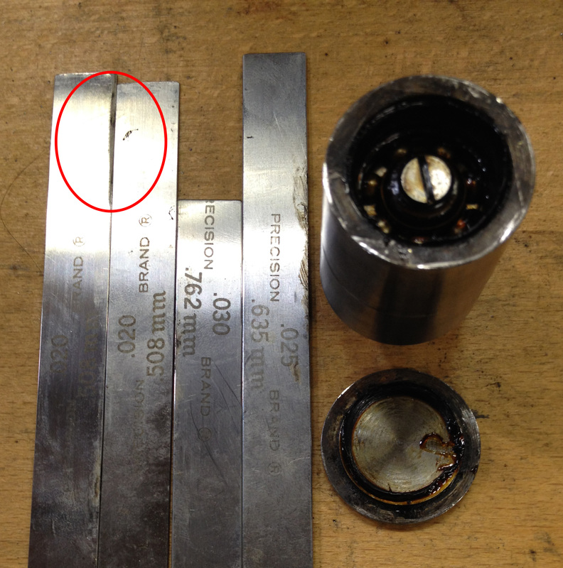
A single edged razor blade did the trick. By using two of them, I forced the gap open a bit wider all the way around. It still wasn't wide enough to lever the cap off or to get any other sort of prying implement into the gap. Then I remembered the stock of random feeler gauge stock I bought off eBay a few months ago.
I grabbed a selection of thicknesses (0.020", 0.025", 0.030") and tried to use them to further open the gap. The 0.020" was still too thick to go into the gap created with the razor blades. So, I filed a knife edge onto one end (in the red oval on rightmost picture) to make it go into the narrow gap. Working the gap open to 0.030" was enough to pop the cover off.
Is that some nasty old bearing grease or what? No wonder this turns so stiffly.
I decided that tapping a stout knife blade into the gap might work...but my bench knife has gone walkabout. Now what?
A single edged razor blade did the trick. By using two of them, I forced the gap open a bit wider all the way around. It still wasn't wide enough to lever the cap off or to get any other sort of prying implement into the gap. Then I remembered the stock of random feeler gauge stock I bought off eBay a few months ago.
I grabbed a selection of thicknesses (0.020", 0.025", 0.030") and tried to use them to further open the gap. The 0.020" was still too thick to go into the gap created with the razor blades. So, I filed a knife edge onto one end (in the red oval on rightmost picture) to make it go into the narrow gap. Working the gap open to 0.030" was enough to pop the cover off.
Is that some nasty old bearing grease or what? No wonder this turns so stiffly.
|
|
|
I scraped out the old grease with a piece of coffee stirrer and wiped out the residue with a rag and some cotton swabs.
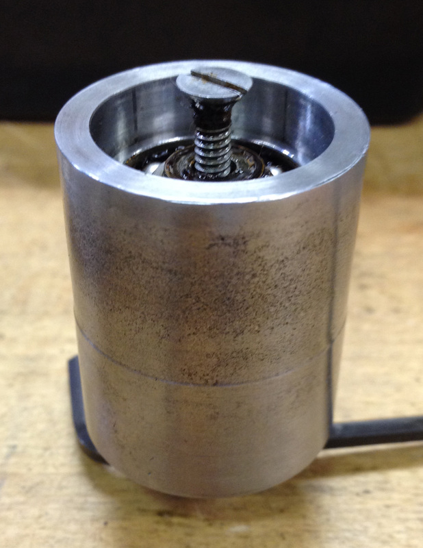
Now the head of the A-123 Retaining screw is clearly visible. |
|
|
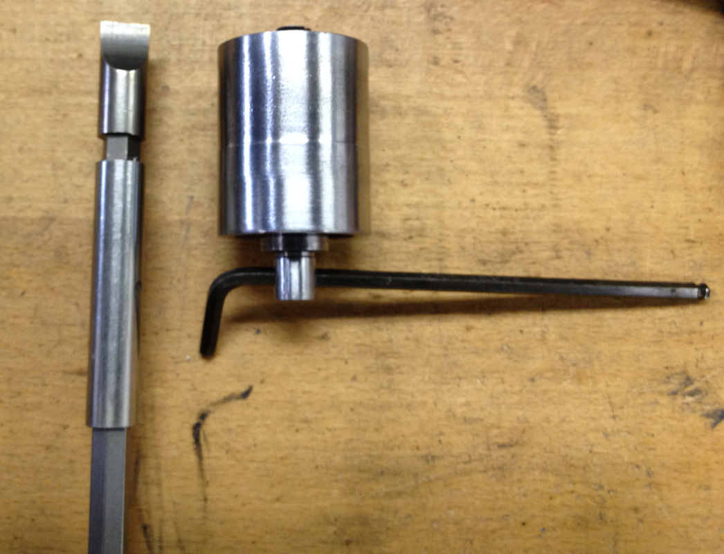
To remove the A-123 Retaining Screw, I put an allen key through the hole in the A-122 Idler Shaft (to keep the shaft from rotating) and found a bit from my Brownell's Magna-Tip screwdriver kit to match the slot in the screw head.
I didn't want to mar the screw slot if it took a lot of force to remove the screw and the hollow ground blades of the Magna-Tip screwdrivers are great for preventing bozo marks...if you have one that fits the screw slot closely. |
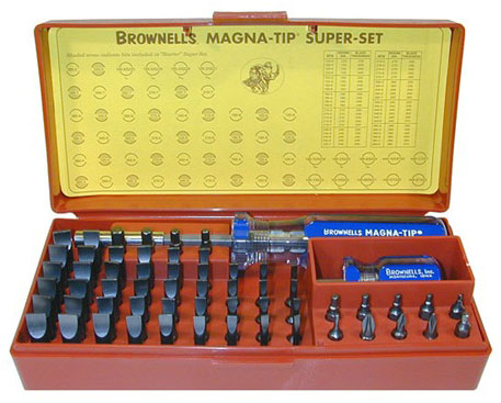
image from brownells.com
|
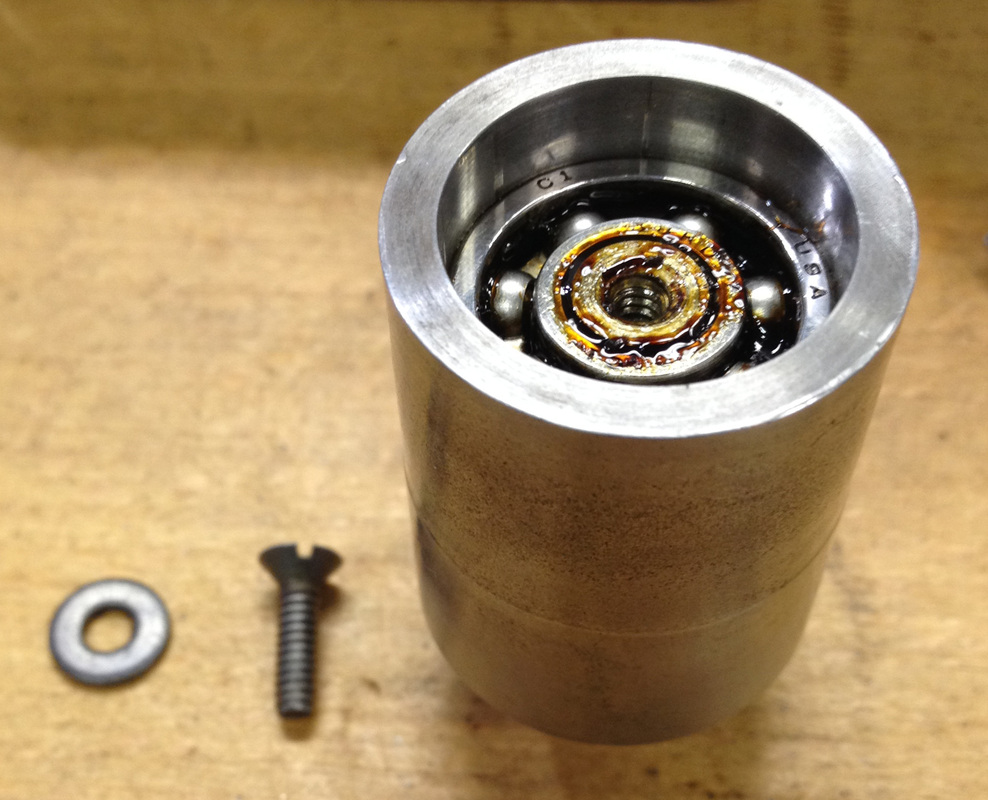
Turns out I didn't need to worry. The A-123 Retaining Screw came right out...and it turned out to be a flat head slotted machine screw.
A bit of an odd choice given the application. I wonder if it is a replacement part.
Perhaps I'll replace it with a more suitable pan head screw or SHCS.
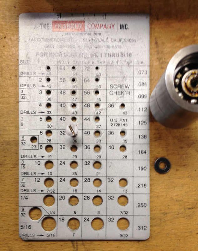
I cleaned off the newly exposed grease as above and verified that the screw is a 6-32 x 1/2".
A bit of an odd choice given the application. I wonder if it is a replacement part.
Perhaps I'll replace it with a more suitable pan head screw or SHCS.
I cleaned off the newly exposed grease as above and verified that the screw is a 6-32 x 1/2".
|
|

|
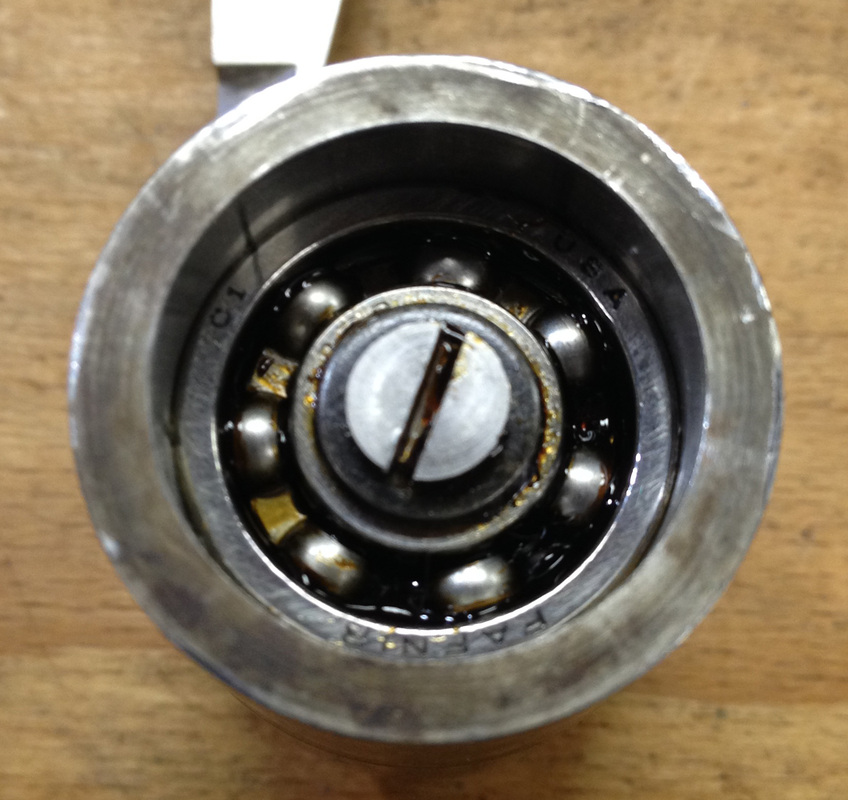
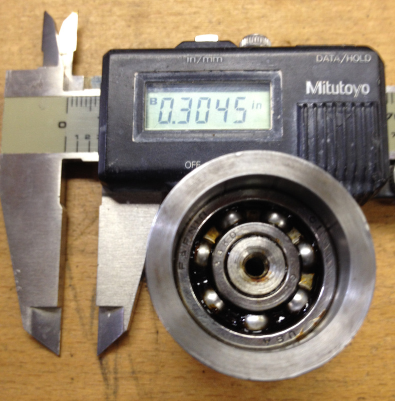
The bearing is 0.228" down from the top lip of the A-108 Belt Tension Idler. The lower bearing is flush with bottom lip.
The ID is 0.866" (22mm) The ID of the bearing inner race is about 0.305" ,but it's hard to measure at this point. Call it 0.315" (8mm). The inner race is marked "C1" and "38KD". Time for a visit to google to see what of bearing info I can find. |
|
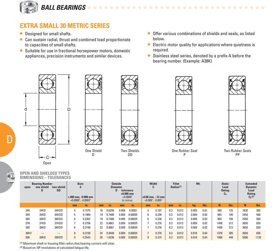
image from timken.com
|
Fafnir is now part of Timken. The Timken site gave up a ball bearing catalog.
I found the bearing on page D6 of the catalog (see image at left). The 38KD is a part of the Extra Small Metric Series of ball bearings. 8mmx22mmx7mm, single shield. More googling indicates that these are about $10-$15 bearings. So, it should be low risk to try to press them out of the A-108 Belt Tension Idler. If I screw them up, I can buy more without going broke. |

|
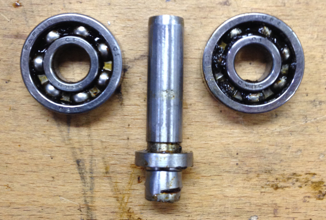
Now that I know what the A-980 Ball Bearings are, how do I get them out of the A-108 Belt Tension Idler?
The answer is...a visit from Mr. Bozo! |
|
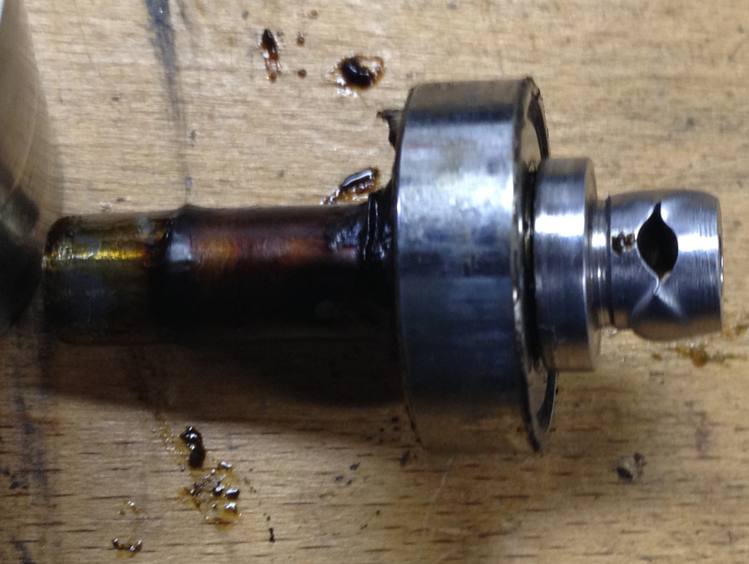
I figured that pressing out the bearings was the obvious answer. But which direction to press them out? Not sure, but the one thing I knew I didn't want to do was mess up the end of the A-122 Idler Shaft with its taper pin hole.
Which, of course, I promptly did. Turns out you can't press on the end of an about 3/8" diameter shaft that has a #0 taper pin hole in it. No kidding, right? Those of you saying "What kind of idiot would even do that?" can now rest easy knowing that it would be an idiot like me. |
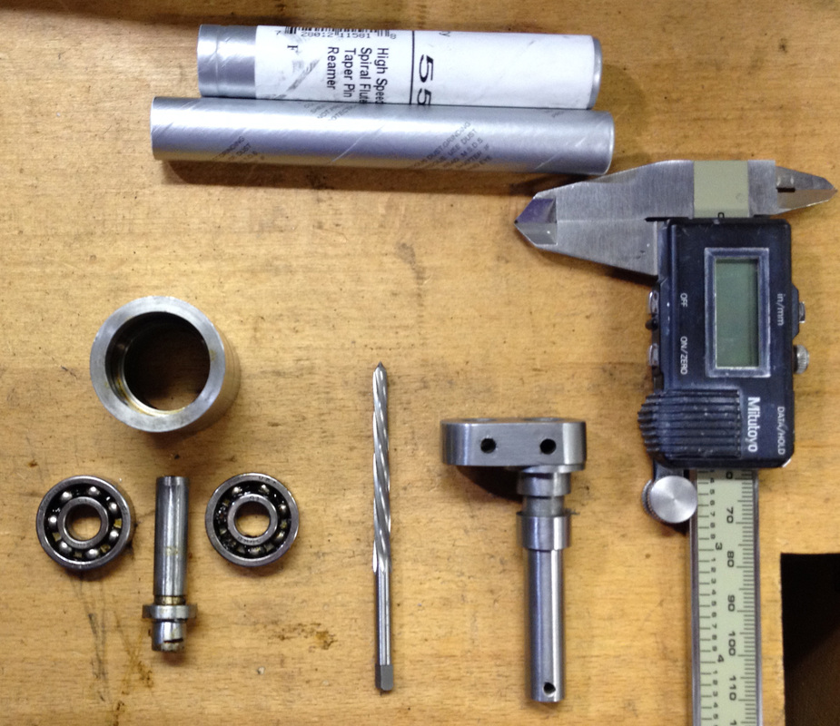
Soooooooo, what next. Well, I better get some new bearings, steel for the shaft, and a #0 taper pin reamer on order.
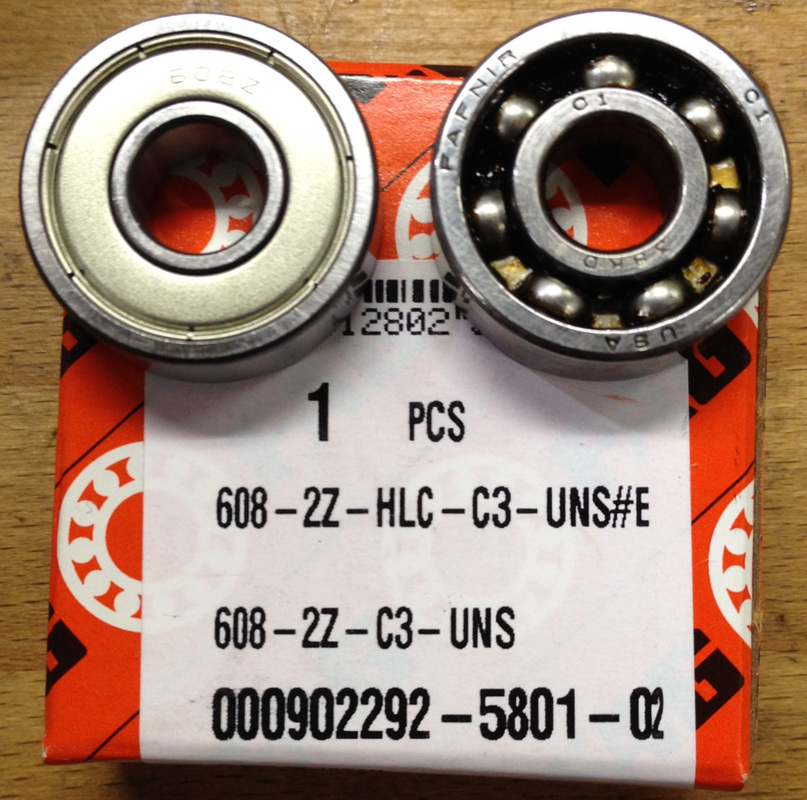
McMaster doesn't have a direct equivalent to the Fafnir 38KD bearings - the single shield isn't a common type. I'll order the 608 double shielded bearings and see how things go. I can get replacement copper hammer faces for the No. 1 BASA Hammer while I'm at it.
With the #0 taper pin small end being 0.140", drilling the pilot at 0.136" (#29) should work. A 0.1405" (#28) would probably end up over size. I'll naturally be practicing the use of the somewhat delicate taper reamer before I try to ream the actual replacement A-122 Idler Shaft.
The shaft has a center in both ends, so it may have been machined between centers.
|
Pressing the shaft and bearings out the rest of the way was simple, after I knew how it all went together.
I found the taper pin reamer I needed on eBay from North Bay Cutting Tools. Ordered on Thursday evening at 10pm, in hand via USPS on Monday morning. Gotta love that. The reamer fits the holes in the A-121 Idler Link perfectly. |
|
The old bearings are pretty ugly. The new ones from McMaster are a lot smoother. That give me hope that all of this messing around is worth it.
|
|
Along with the bearings, McMaster delivered 3 ft. lengths of 1/2" diameter 12L14 and 1144 ("stressproof") for me to play around with. The 12L14 should be easy to work with as usual. I've never machined 1144 so I thought this might be an interesting opportunity to give it a try.
Now I just need a drawing to work from.
Now I just need a drawing to work from.
